Knob & Tube Electrical Info
~~Guide to knob and tube electrical wiring: This article answers basic questions about Knob and Tube electrical wiring. We define knob and tube wiring, we include photographs that aid in recognition of this generation of electrical wiring, and we describe both proper and improper K&T wiring installations, repairs, or circuit extensions.
Knob-and-tube wiring in older homes: description, inspection, repair
Knob-and-tube wiring in older homes: description, inspection, repair
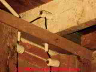
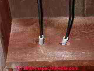
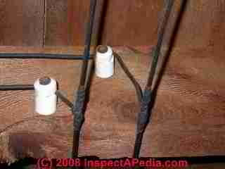
Knob and tube electrical of wiring has been installed in homes from the 1920s right up into the 1970's in some jurisdictions. Our photos above will assist homeowners and inspectors in recognizing this wiring method.
Article Contents
• KNOB & TUBE WIRING of Proper and Improper Knob and Tube Wiring Details
o Illustrations
o Effects of Building Insulation on Knob and Tube Electrical Circuit Safety
o Safety & Electrical Code Concerns with Knob and Tube Electrical Circuits that Have been Extended or Spliced-into
o Advice about improving the safety and reliability of knob and tube electrical wiring
Characteristics & Safety Considerations of a knob and tube electrical circuit
• No ground: Only a hot and neutral wire are provided. Watch out: A knob and tube electrical circuit has no electrical ground path.
• Wire insulation: The individual electrical wires are wrapped in a rubberized cloth. That was fine when the wires remained suspended in air and had not been chewed by a squirrel.
• Knob and tube wiring connections or splices were made outside of electrical junction boxes. In normal practice knob and tube wiring splices are soldered and also taped.
We describe these splices at "Taps" in ELECTRICAL SPLICES, HOW TO MAKE.
• Ceramic tubes to route knob and tube electrical wires through building framing members: Wherever the knob and tube circuit wires pass through building framing lumber a ceramic tube is used to insulate the wire from the wood. These thick ceramic tubes are a good insulator separating electrical wire from wood - if both are un-damaged. Our photo at left shows knob and tube electrical wiring in the Justin Morril Smith historic home in Strafford VT. Also see our earlier photo at above right where electrical wires pass through a wall top plate in a 1920 home.
• Ceramic knobs to support knob and tube electrical wires passing over building framing surfaces: Where the knob and tube wiring is surface mounted in a building it is attached using a ceramic "knob".
These ceramic knobs are a good insulator provided they have not been damaged or modified.
• Our photo at left shows knob and tube electrical wiring in the Justin Morril Smith historic home in Strafford VT. Also see ceramic tubes supporting knob and tube circuits in other photos and sketches on this page.
• Our photo at left shows knob and tube electrical wiring in the Justin Morril Smith historic home in Strafford VT. Also see ceramic tubes supporting knob and tube circuits in other photos and sketches on this page.
Illustrations of Proper and Improper Knob and Tube Wiring Details
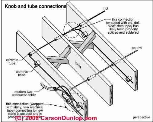
The sketch at left shows the usual ways that knob and tube electrical wiring is connected in homes.
• Knob and tube electrical circuits are not "illegal" and there is not a code requirement that they be replaced. However this wiring method is considered obsolete.
• No electrical ground is provided - the circuit is less safe than a modern grounded electrical circuit and appliances and devices that use a grounded plug should not be connected on an un-grounded circuit.
• The knob and tube wiring may have become damaged by age, exposure to leaks, or to chewing rodents. In attics, for example, we often see that this wiring has been damaged by having been stepped-on or by chewing rodents.
• The safety of the knob and tube circuit may have been affected by building changes such as adding insulation (discussed next) and modifications to the original circuit (discussed below).
Effect of Building Insulation on Knob and Tube Electrical Circuit Safety
• Adding building Insulation changes the knob and tube wire game: The fire safety of knob and tube wiring relied on the fact that the wires were generally routed through the air, suspended by knobs and protected by a heavy ceramic tube where passing through wood.
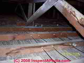
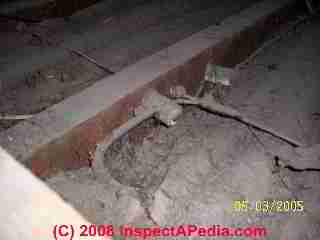
The two photos above show a knob and tube circuit that has not been covered with insulation (though we wonder about the significance of those leak stains on the ceiling joist forming the attic floor), while the knob and tube circuit in the right photo has been partly buried in blown-in cellulose insulation.
We pose that the same insulation project may have filled wall cavities with insulation too, possibly leading to overheating of knob and tube circuits that run in the building's exterior walls. We're also concerned that where knob and tube wires have been run in an attic floor and later covered by insulation, there's a good chance that someone walking in the attic has stepped-on and damaged the wires - a condition we've found often.
Where such wires were routed in walls or in attic floors, and where later those building cavities have been insulated, the knob and tube wires are no longer suspended in air, can become hotter than intended, and may be a fire hazard for that reason.
Safety & Electrical Code Concerns with Knob and Tube Electrical Circuits that Have been Extended or Spliced-into
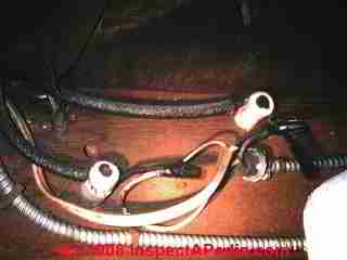
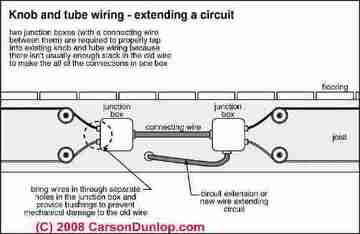
The photo at below left shows a combination of errors, extending a knob and tube electrical circuit and a twist on connector electrical splice outside of an electrical junction box. The photo also shows three types of electrical circuit wiring: knob-and-tube, armored "BX" cable, and plastic cable wires. The photo shows therefore three generations of electrical wiring (and probably other modifications) in this building. Carson Dunlop's sketch at below right shows how these circuits might be extended.
• Often the knob and tube circuit has been modified or extended by subsequent building owners/occupants - an improper practice that is not permitted in most codes.
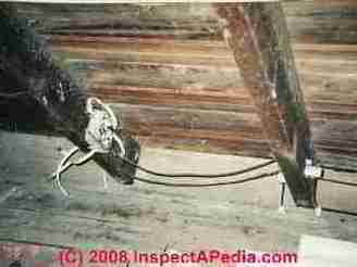
The photo at the top of this page shows an inspection client pointing to a modern plastic NM electrical cable that has been used to extend an older knob and tube electrical circuit.
In some jurisdictions, extending an existing knob and tube circuit is not recommended, and is even an illegal installation: by adding load to the knob and tube circuit, risks increasing the temperature of the wiring and possibly causing a fire.
Advice about improving the safety and reliability of knob and tube electrical wiring
• Inspect the whole electrical: An expert should inspect the condition of the building electrical wiring, including the wires, connections, devices like receptacles, switches, and overcurrent protection by fuses or circuit breakers.
• Replace bad circuits: Knob and tube circuits that have been modified, damaged, or covered with insulation should be replaced with a modern grounded electrical circuit.
• Ground fault protection GFCI circuit protection and possibly arc fault protection can be added on two-wire un-grounded electrical circuits to reduce the chances of electrical shock or fire - steps that we recommend.
See AFCIs ARC FAULT CIRCUIT INTERRUPTERS. (A homeowner cannot safely test a GFCI while it is in place, installed on an electrical circuit that has no ground but the GFCI can still be expected to work correctly if it is wired properly.)

